Enhanced structural stability of yttria-stabilized zirconia–LaMgAl11O19 dual ceramic coating by an α-Al2O3 layer
Haotian Tao and Tianxin Liu have contributed equally to this work.
Abstract
To prolong the service life and structural stability of CoCrNiAlY–yttria stabilized zirconia–LaMgAl11O19 (LaMA) dual ceramic coating during high temperature exposure, an AlY plating layer was deposited on top LaMA. Results revealed that this coating without AlY plating layer showed a rapid mass increase from 6.62 mg/cm2 at 20 h to 10.63 mg/cm2 at 80 h, but also suffered from a fast TGO growth and severe elemental diffusion, resulting in an exacerbating interface fracture of the coating. However, AlY plating layer was first oxidized, and Y2O3 induced the formation of a dense α-Al2O3 reaction layer on the top LaMA layer, which greatly prevented the internal penetration of O2. This coating with AlY plating layer showed a relatively stable structure, a very slow TGO growth, and a slight mass increase trend from 8.19 mg/cm2 at 20 h to 8.73 mg/cm2 at 80 h. Potential oxidation damage mechanisms of the coatings with or without AlY plating layer were comprehensively clarified.
1 INTRODUCTION
Thermal barrier coatings (TBCs) are widely used to protect high temperature hot end components due to their high temperature oxidation resistance and low thermal conductivity.1, 2 Yttria-stabilized zirconia (YSZ) is currently one of the most used ceramic coating material, but it is prone to sintering and phase transformation accompanied by 4%–6% volume expansion as the operating temperature increases, which eventually leads to premature failure of TBCs.3-5 Recently, many researchers developed an integrated design of the structure and material. Double-layer TBCs consisting of a ceramic surface layer and a YSZ intermediate layer have become a promising development trend. Literature confirmed6 that the thermal cycle life of double ceramic layer is greatly enhanced in comparison to single ceramic layer.
LaMgAl11O19 (LaMA) has low thermal conductivity, high fracture toughness, and moderate coefficient of thermal expansion, which makes it one of the most promising candidate materials for ceramic surface layer.7-9 However, fast heating and cooling cycling during the spraying process leads to many amorphous phases in the LaMA, which seriously affects the reliability of the coating.10-12 Huang et al.13 reported that LaMA underwent a significant crystallization and volume shrinkage at 900 and 1174.9°C resulting in the initiation of numerous micro-cracks. Although larger porosity had a certain improvement in its strain resistance and insulation performance, but these micro-cracks acted as the infiltration channels of oxygen during high-temperature exposure, accelerating the rapid internal diffusion of O2 and molten salt, and eventually led to a systemic instability and fracture failure of LaMA layer.
To suppress the volume shrinkage of LaMA coating, Sun et al.14 reduced the amorphous phase by doping Gd2O3, but this method was unable to eliminate the negative effect of volume shrinkage of LaMA resulting in very limit improvement in thermal cycling lifetime. In contrast, the sealing layer has been proved to be a viable strategy to enhance the service life of the TBCs. Zohre Soleimanipour et al.15 created an Al2O3 layer on the surface of YSZ by laser cladding. They found that this surface layer has dense structure, without pores or cracks, and extended the service life of TBCs. Morover, Xu et al.16 found that Al2O3 barrier layer enhanced the oxidation resistance of the coating but mainly existed in the form of sub-stable θ-Al2O3 at lower temperature or in the initial stages of oxidation test. It has been reported that the addition of Y facilitates the generation of a more dense and stable α-Al2O3 at lower temperature,17 which provides a feasible strategy for the fabrication of a dense α-Al2O3 barrier layer. Herein, an AlY plating layer was deposited on the surface of CoCrNiAlY–YSZ–LaMA dual-ceramic coating. The structural evolution of AlY plating layer during high temperature air exposure was investigated by detail characterizations. The effects of reaction barrier layer on the oxidation behavior of the coating were systematically investigated.
2 MATERIALS AND METHODS
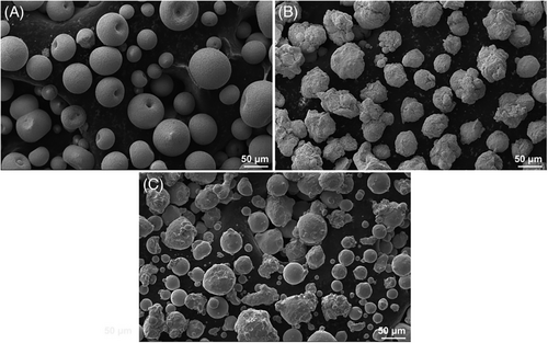
The GH188 super-alloy, with dimensions of 15 mm × 15 mm × 5 mm, served as the substrate in this work. Its chemical composition is shown in Table 1. The sample surface was cleaned with alcohol in an ultrasonic bath before coating to remove oxides. After that corundum pellets (240 mesh) were used to sandblast each sample. Atmospheric plasma spraying (APS) technology is used to prepare CoCrNiAlY–YSZ–LaMA dual ceramic coatings on substrates. The CoCrNiAlY powder contains 31.0–34.0 Ni, 24.5–26.5 Cr, 5.0–6.5 Al, and .4–.8 Y in wt.%, with the remaining material being Co. The YSZ powder included balanced ZrO2 and the 7.0–7.5 wt.% Y2O3. The LaMA powder had 15.0–24.0 La2O3, 4.0–7.0 La2O3, 4.0–7.0 MgO in wt.%, and balanced Al2O3. The morphologies of LaMA, YSZ, and CoCrNiAlY powders are shown in Figure 1, with particle sizes of 30–74, 30–64, and 32–125 µm, respectively. The working gases were high grade hydrogen (99.9 at.%) and argon (99.9 at.%). Table 2 is the list of the APS process specifications.
| Elementary | C | Si | Cr | Ni | W | Mn | La | Co |
|---|---|---|---|---|---|---|---|---|
| Composition (%) | .05–.15 | .20–.50 | 20.0–24.0 | 20.0–24.0 | 13.0–16.0 | ≤1.25 | .03-.12 | balanced |
| Process parameters | CoCrNiAlY | YSZ | LaMA |
|---|---|---|---|
| Thickness (µm) | 100–120 | 180–200 | 100 |
| Current (A) | 500 | 600 | 600 |
| Distance (mm) | 120 | 120 | 120 |
| Line speed (mm/min) | 800 | 800 | 800 |
- Abbreviation : YSZ, yttria stabilized zirconia.
Arc ion plating is used to deposit an AlY layer on top of a LaMA layer. The Y content in AlY target material is 3 wt.%, with a thickness of 20 µm. The current is 80 A, the bias voltage is −80 V, and the deposition time is 60 min. The design schemes of TBCs are reported in Table 3.
| Sample | Coatings |
|---|---|
| Y1 | CoCrNiAlY–YSZ–LaMA |
| Y2 | CoCrNiAlY–YSZ–LaMA–AlY |
- Abbreviation : YSZ, yttria stabilized zirconia.
Using a high-temperature muffle furnace, the oxidation behavior of all samples exposed to air was investigated. At a heating rate of 10°C/min, a dwell duration of 80 h, and a service temperature of 1000°C. Using a balance with an accuracy of 10−4 g, the mass change of each sample was tracked and analyzed the trend of sample weight gain. The phase structure variations of the coating following the oxidation test were investigated by X-ray diffraction (XRD, X'Pert Powder). Scanning electron microscopy (SEM, Zeiss SIGMA HD) was used to analyze the surface and cross-sectional microstructure of the coatings. Energy-dispersive spectroscopy (EDS) was used to comprehensively observe and analyze the surface interface elemental distribution of the coating.
SEM (Zeiss SIGMA HD) was used to analyze the surface and cross-sectional microstructure of the coatings.
3 RESULTS AND DISCUSSION
The XRD characterization results of all coatings are displayed in Figure 2. As shown in Figure 2A, according to the standard card number 26-0873, these strong LaMgAl11O19 diffraction peaks have been detected in sample Y1, and clear broad humps were also observed (2θ = 25–40°) in XRD patterns, which is caused by the amorphous LaMA, when the molten droplets of LaMA are deposited onto the cold substrate, particles that are well-melted readily form the amorphous phase.
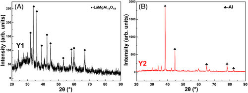
In contrast, only some weak LaMgAl11O19 diffraction peaks are identified in sample Y2, as shown in Figure 2B, but these strong diffraction peaks are mainly attributed to these Al phases referring to the standard card number 85-1327. These characteristic peaks of Y phases are hardly detected due to its relatively low content.
Figure 3 displays the SEM images of all coatings. As shown in Figure 3A, sample Y1 exhibits a relatively dense surface, but some visible holes and micro-cracks are clearly observed, which are accordance with the intrinsic structural feature of APS coating. Moreover, a clear three-layer structure consisting of CoCrNiAlY, YSZ, and LaMA is characterized in the cross-sectional image of sample Y1, and these component layers exhibit good interface bonding (Figure 3B). As shown in Figure 3C, sample Y2 exhibits a cauliflower-like surface morphology, and AlY layer effectively fills these micro-crack defects. The EDS regional analysis further confirms the existence of AlY layer on the LaMA. In addition, the AlY layer is well bound to the top LaMA layer (see Figure 3D).
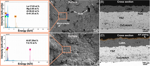
Figure 4A shows the mass grain values of all coatings in the range of 20–80 h oxidation tests. The mass gain value of sample Y2 is .530 mg/cm2, which was much lower than that of sample Y1 (4.017 mg/cm2), indicating a better antioxidant performance. The weight gain curves and optical images during the oxidation tests are shown in Figure 4B. It can be seen that samples Y1 show a continuously rapid weight gain with the increase of oxidation time, indicating an aggravated oxidation reaction. Sample Y2 possesses a high mass gain value during the first 20 h (8.19 mg/cm2) due to a sufficient oxidation of AlY layer, but remains a very slow mass gain trend during the rest oxidation test, proving an improved oxidation resistance.
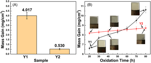
Figure 5 shows the XRD characterization results of all coatings after the oxidation tests at 1000°C. As displayed in Figure 5A, according to the standard cards of 26-0873 and 43-0923, sample Y1 is mainly composed of LaMA phases, but the intensities of LaMA phases gradually increase with the increase of oxidation time, indicating an accelerated crystallization reaction.18 Meanwhile, a small amount of LaAlO3 phase appears in the XRD pattern, which likely originates from high temperature decomposition of LaMA phase. As shown in Figure 5B, LaMA and LaAlO3 phases are also identified in sample Y2, but a large amount of α-Al2O3 phase (PDF46-1212) is detected in this XRD pattern, confirming that an in situ α-Al2O3 reaction film forms on the top LaMA layer.
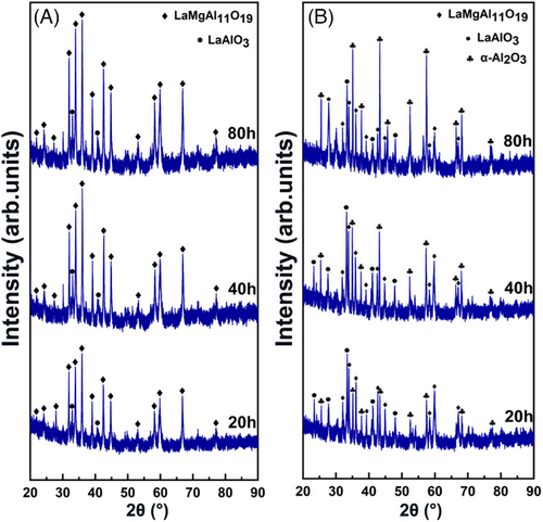
Figure 6 shows the SEM images of all coatings after 20 h oxidation tests at 1000°C. As displayed in Figure 6A, some network micro-cracks with a width of up to 3.45 µm distribute on the surface of sample Y1. Figure 6B reveals that longitudinal micro-cracks form in the LaMA layer and gradually extend to the YSZ layer. Moreover, transverse micro-cracks appear at the junction of YSZ and CoCrNiAlY. In contrast, sample Y2 shows a dense scale like surface morphology (see Figure 6C), which is accordance with a typical morphological feature of α-Al2O3.17 As shown in Figure 6D, although LaMA layer suffers from a significant fracture damage, these component layers remain good interface bonding. Apparently, the existence of the in suit α-Al2O3 layer changes the fracture pattern as well as stress distribution of the LaMA tissue and effectively alleviates the damage of the double ceramic coating.
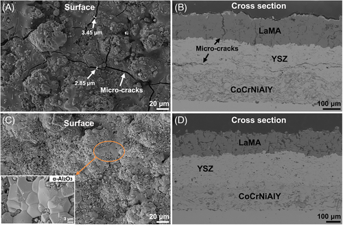
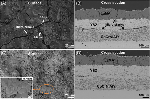
Figure 7 shows the SEM images of all coatings after 40 h oxidation tests. These cracks are obviously distributed on the surface of sample Y1, but the crack width is up to 5.44 µm (Figure 7A), hinting an aggravated fracture of LaMA. The transverse crack in YSZ layer also shows a rapid propagation with extended oxidation time (Figure 7B), indicating a deteriorating structural stability of dual ceramic coating. In comparison, sample Y2 shows a relatively dense surface accompanied with a large area α-Al2O3 (Figure 7C) but also maintains relatively stable structure although YSZ layer suffers from a slight local fracture damage (Figure 7D).
The structural damage of sample Y1 is aggravated after 80 h oxidation tests. The width of micro-cracks in LaMA is up to 10.68 µm (Figure 8A). Further extension of longitudinal cracks occurs and thus results in local fracture in the YSZ bonding layer, as shown in Figure 8B, transverse penetration cracks also form at the junction of YSZ and CoCrNiAlY, illustrating a severe structural failure. In comparison, sample Y2 still remains relatively dense surface after 80 h of oxidation test, as shown in Figure 8C, LaMA layer suffers from a slight fracture damage, and these local α-Al2O3 are clearly observed on the coating surface. Although a few transverse micro-cracks form in the YSZ layer, but this coating structure is relatively stable with good interface adhesion (Figure 8D). The local EDS elemental mapping analysis of Figure 6E clearly reveals that a continuous α-Al2O3 enrichment layer forms on the LaMA, which effectively seals the micro-cracks induced by crystallization reaction of LaMA.
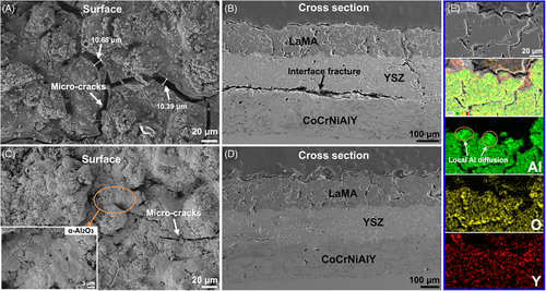
Figure 9 shows the TGO layer morphology evolution of all coatings at different oxidation time. As displayed in Figure 9A, a black TGO layer is formed in sample Y1 after 20 h oxidation test. However, a gray diffusion layer appears above the black TGO layer after the 40 h oxidation test (Figure 9B), indicating an accelerated element diffusion trend. This black TGO layer becomes discontinuous after the 80 h oxidation test, whereas the gray TGO layer shows a rapid upward diffusion during the oxidation test (Figure 9C). In contrast, sample Y2 shows a very slow elemental diffusion and TGO growth during the oxidation test. A single thin black TGO layer is formed after 20 h oxidation test (Figure 9D), but the thickness did not change significantly after 40 h oxidation test (Figure 9E) as the oxidation time reaches 80 h, a thinner gray TGO layer appears, but the black TGO layer remained continuous morphology (Figure 9F).
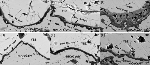
Figure 10 shows SEM and EDS characterization results of TGO layer in all coatings after 80 h oxidation tests. The element compositions of the selected region in the TGO layer are presented in Table 4. Sample Y1 experiences a severe elemental diffusion during the 80 h oxidation test, forming a composite TGO layer with a thickness of about 8 µm (Figure 10A,b). The selected region 1 in gray TGO layer (Figure 10C) has high Cr (43.07 at.%) and O (21.29 at.%) contents, whereas region 2 in black TGO layer (Figure 10C) has high Al (40.42 at.%) and O (28.51 at.%) contents. Based on previous literature,19 Al2O3 makes up the bottom black oxide layer, whereas (Ni, Co)Cr2O4 is mostly responsible for the gray oxide layer. As seen in Figure 10D,E, sample Y2 experiences a slight elemental diffusion during the 80 h oxidation test, evidenced by a thicker black TGO layer and a thinner gray TGO layer. The selected regions 3 and 4 (Figure 10F) confirm that the black and gray layers predominantly belong to Al2O3 and (Ni, Co)Cr2O4, respectively. These EDS characterization data clearly demonstrate that the α-Al2O3 reaction layer significantly reduces elemental diffusion and TGO development during the oxidation tests and eventually enhances the structural stability of dual ceramic coating.
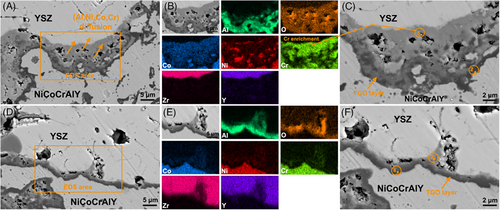
| Region | Co | Cr | Ni | Al | Y | O |
|---|---|---|---|---|---|---|
| 1 | 27.04 | 43.07 | 6.35 | 1.22 | 1.03 | 21.29 |
| 2 | 10.10 | 11.90 | 8.18 | 40.42 | .88 | 28.51 |
| 3 | 8.44 | 35.18 | 7.69 | 18.46 | 1.36 | 28.87 |
| 4 | 6.99 | 5.42 | 5.98 | 54.33 | 1.46 | 25.82 |
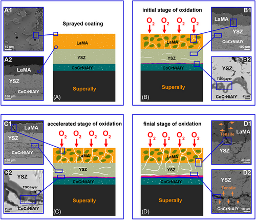
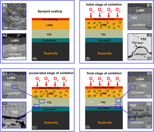
The structural damage of LaMA layer becomes more severe with the oxidation time increases, as shown in Figure 11D and D1, these longitudinal cracks initiated in the LaMA layer extend to the YSZ layer, degrading the barrier layer of the coating, and thus result in an aggravated oxidative attack. The Al depletion is intensified in the final stage of oxidation test, whereas Ni, Cr, and Co diffuse outward more severely, which leads to higher growth stresses. The synergistic effect of crystallization stress in the top layer and growth stress in the TGO layer eventually results in a large-scale long transverse fracture failure (Figure 11D2).
4 CONCLUSIONS
This work investigated the effect of an AlY plating layer on the oxidation behavior and structural stability of CoCrNiAlY–YSZ–LaMA dual ceramic coating. Numerous holes or cracks formed in the sprayed coating. Plenty of longitudinal micro-cracks also appeared in LaMA due to a recrystallization-induced volume shrinkage. These inherent and initiated defects offered the inward diffusion channels of O2, triggering a rapid interface oxidation process, and thus led to accelerated creation of brittle (Ni, Co)Cr2O4 phase, fast growth of TGO layer, sustained mass gain, and severe coating fracture. However, the dual ceramic coating with an AlY plating layer showed improved oxidation resistance and structural stability during high temperature air exposure. A dense α-Al2O3 layer formed on the LaMA, which successfully blocks O2 inward transport, as well as the quick development and high stress initiation of TGO layer, and eventually resulted in low mass gain and relatively stable structure.
ACKNOWLEDGMENTS
This study was supported by the University of Science and Technology Liaoning Talent Project Grants (601011507-07). The authors would like to thank all the reviewers who participated in the review.
CONFLICT OF INTEREST STATEMENT
The authors declare that they have no known conflict financial interests or personal relationships that could have appeared to influence the work reported in this paper.


